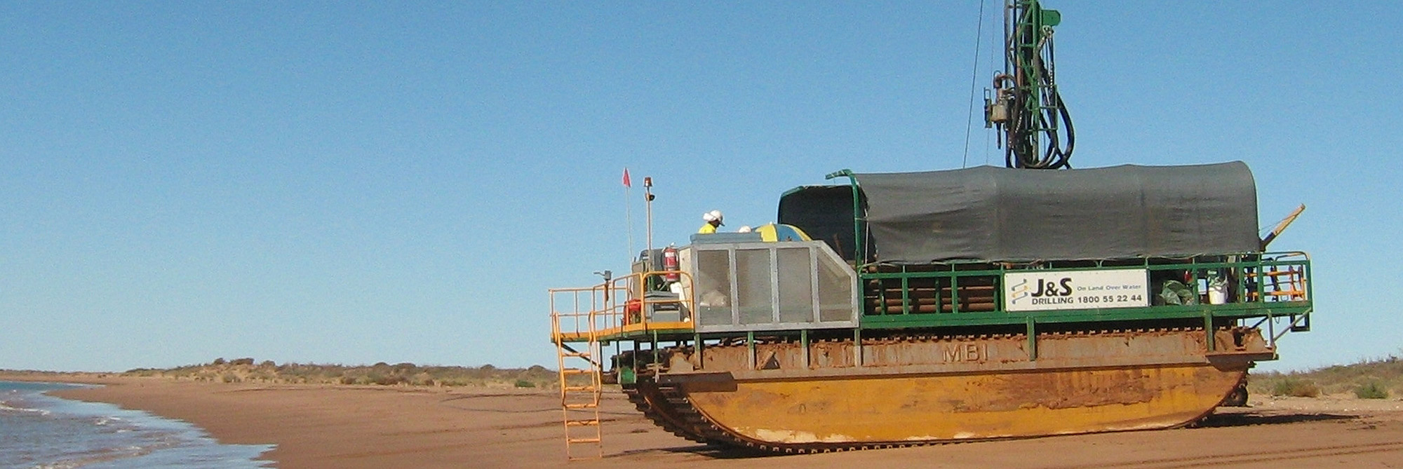
J&S Drilling has recently completed a series of Irrigation Bores & Pump Testing in the Central Queensland region. The Bores were drilled using 12” mud rotary techniques to stabilise the hole. Thus allowing for the installation of PVC bore casing and Stainless Steel screens to maximise water entry.
Environmental considerations
A mission 4×3 mud pump was utilised to assist in the clearing of cutting. A Mud Puppy (de-sanding unit) recycled the drill mud to minimise environmental impacts. This also ensured a clean and stable borehole for the installation of the production casing.
The drilling mud mixtures were carefully selected to ensure hole stability and maximise penetration rates. J&S Drilling utilised Aus-Gel Xtra and PAC-R drilling additives. The mud mixtures were monitored for their viscosity using a Marsh Funnel. Other products were used to bring the pH to the correct level ensuring the muds were mixed to the OEM specifications.
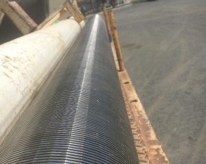
Stainless steel screens
Stainless steel screens were selected to maximise efficiency of the well and to suit the formation natural gravel size. 1.5mm and 2.0mm aperture screens were installed in the irrigation bores. The bores were chemically back flushed with chlorine, well clean and liquid sperse to break down drill muds. Subsequently returning the ground water to its natural state before development.
The Annulus between the bore casing/ screens and the borehole consisted of gravel pack around the screen. Followed by a bentonite chips seal in the clay layer. With S.G 1.64 cement/ grout slurry pumped via tremmie line from the bentonite seal layer to the surface. Grout was then left to cure for 24 hours before development could take place.
Bore Development
The irrigation bores were developed using an Edson drill rig, and compressor. A jetting tool was used on the end of the drill rods to allow for the compressed air to jet directly into the openings in the stainless steel screen. This encouraged the fine silt, sand and residue drill mud to pass through the screen. Leaving a uniform gravel pack around the screen. The bores were developed using this methodology for 5-6 hours until there were no visible signs of silt.
Once the Static Water Level (SWL) had recharged after development, a 6” submersible pump was lowered into the hole in preparation for pump testing.
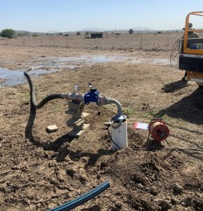
Pump Testing
Pump testing began with step tests to ascertain the ideal pumping rate before starting a constant rate pump test. Once the Ideal pump rate was identified in the step test, the submersible pump was shut off and the SWL was left to recharge to its natural state. Once recharged, the constant rate pump test started, and measurements were taken using an electronic water level reader. These measurements assist in monitoring the drawdown of the water level and subsequent maximum pumping rate of the bore. Flow readings were taken through a 3” orifice flow metre and this allowed for accurate readings when pumping.
In conclusion, information was given to the property owners about the maximum pumping rate of the bores so they were able to select a suitable pumps to irrigate their properties.